Introduction
The Boeing 767 has always been somewhat neglected when it comes
to flight simulation hardware. Indeed,
almost every single hardware manufacturer will produce some sort
of product designed for a Boeing 737 or a
Cessna; the 767, however, has been shunned and, to a degree,
ignored by cockpit-building companies since it's
not as popular as its smaller counterpart. Unfortunately, there
are very few true Boeing 767 hardware
products available on the market.
Opencockpits, a reputable hardware manufacturer based in Spain,
have broken the mold and produced a
small series of Boeing 767 USB modules which are compatible with
X-Plane, FS2004 and FSX. These modules
are the first of their kind on the market; to my knowledge, not
a single other hardware company regularly
produces 767 USB modules at consumer prices.
The modules produced by Opencockpits include a CDU, a COMM
module, a Transponder module and a NAV
module. All of these modules connect to a computer via USB, and
are powered by the legendary “SIOC”
software, available free of charge from Opencockpits' website.
Whilst there is a range of products available, this review is
based upon the Boeing 767 COMM module. The
COMM radio, which stands for communication, is an aircraft's
primary means of talking to air traffic control.
The Boeing 767 carries two identical COMM radios, appropriately
named COMM 1 and COMM 2. Opencockpits
have replicated the Boeing 767's COMM module to fine detail, and
have made it useable for the average
“simmer” through the medium of USB.
The Basics – Purchase
Information and Specifications
The Boeing 767 USB COMM Module is available for £112. However,
this price is tax free, so it's closer to £151
when one adds tax and shipping to the price (based upon a buyer
who lives in the UK). This price is fairly
reasonable as far as USB modules go; most USB products available
on the market today are equal to, or in
excess of around £150.
Payments are handled securely through either a bank transfer or
PayPal. Opencockpits' site is verified by
PayPal themselves and several other transaction establishments,
so one can have peace of mind when
ordering an Opencockpits product.
For myself, the Module took just over a week to arrive from
Spain. Not bad, I thought, considering that I had
it sent through simple standard postage; with priority shipping,
it probably would have arrived within 5 days.
Alternatively, you can purchase the COMM module from Aviation
Megastore, but I wouldn't recommend this
since their shipping prices are unusually high.
The Opencockpits Boeing 767 COMM module boasts the following
specifications:
● Faithful replica of a Boeing 767 COMM module, produced for
MSFS and X-Plane
● Totally USB Driven; only one cable is required to use the
module
● Fully Backlit
● Driven through Opencockpits' SIOC software, or through
“IOCModules” software
● CNC Engraved panel complete with real-world “DZUS” sockets*
● Fully functional TFR and TEST buttons
● Brightness of 7-Segment Radio Displays can be controlled
through software
● Controlled through the SIOC software
● USB Cable included as standard
[*DZUS fasteners are special screws used in real world aircraft,
and are characteristic of the Boeing 767. The
COMM module includes the sockets for the DZUS fasteners, but not
the actual screws themselves.]
Perhaps the most interesting thing to note just from the
specifications is that is is fully backlit. Almost every
single USB module available in the same price range is not
backlit. What's even more interesting is that the
power supplied through the USB cable is both enough to power the
module itself and the backlighting.
First Impressions
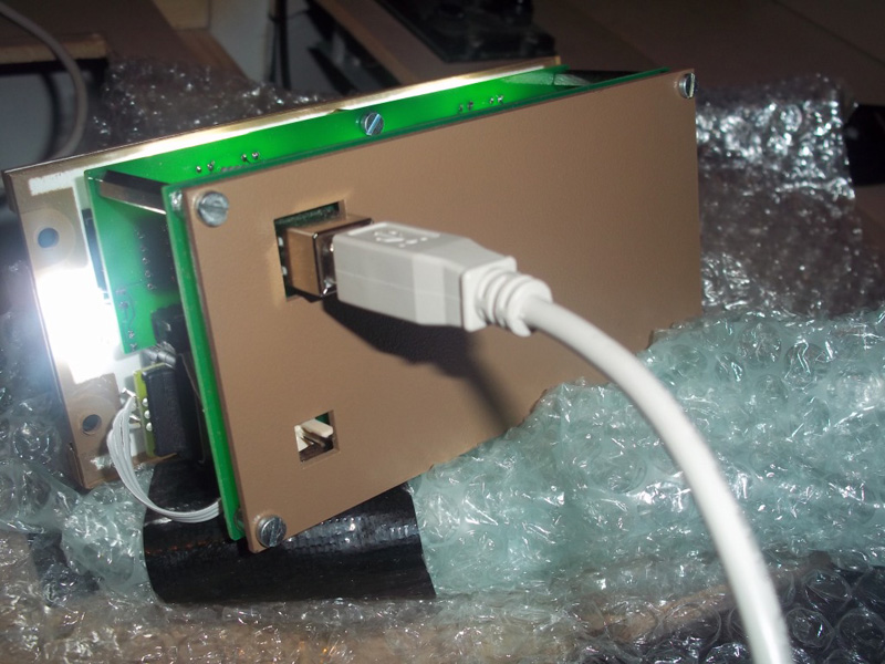
After opening the box, I was greeted by an impressive array of
bubble wrap and polystyrene foam; clearly,
Opencockpits have gone to great measures to ensure that the
modules are not damaged in transit.
As always with Opencockpits' products, the first thing to catch
my attention was the fact that a USB cable is
supplied as standard with the product. A small gesture perhaps,
but something that not many manufacturers
do these days.
The 767 COMM Module arrived ready constructed and ready to use;
all that was left to do was actually plug it
into my PC.
On other thing that should be noted is that fact that, whilst it
is a complete module, the COMM radio has no
“casing” and so its PCB (Printed Circuit Board) and other
internal electronics are somewhat exposed to the
elements. The module is, however, intended to be fitted into
panels, and so a casing would make this task
more difficult to achieve.
Construction
The module's build quality is fantastic.
The frame is entirely constructed from CNC cut aluminum, and the
faceplate is made from Boeing style CNC
cut plastic. The faceplate is constructed from this special
plastic to ensure that the backlighting achieves the
notorious “glow” of backlit panels (see below); a metal
faceplate cannot achieve this, since metal is opaque
and not permeable to light.
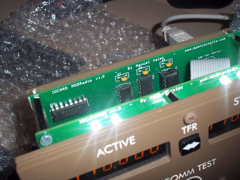
Behind the faceplate, the module's electronics can be found held
securely in place. Thankfully, all of the
module's wiring is kept strictly tidy and all connections are
affixed firmly to the custom-built PCB.
The whole module really has a “firm” feel about it; everything
has its place and nothing rattles when one
moves the module from place to place.
Getting Started – Testing the Module
The insertion of the 767 COMM module into your computer via USB
will immediately start the driver
installation process. As previously mentioned, no drivers are
required to be downloaded from Opencockpits'
site; the exception being that the user must download SIOC
(and/or the “IOCModules Software”; see later).
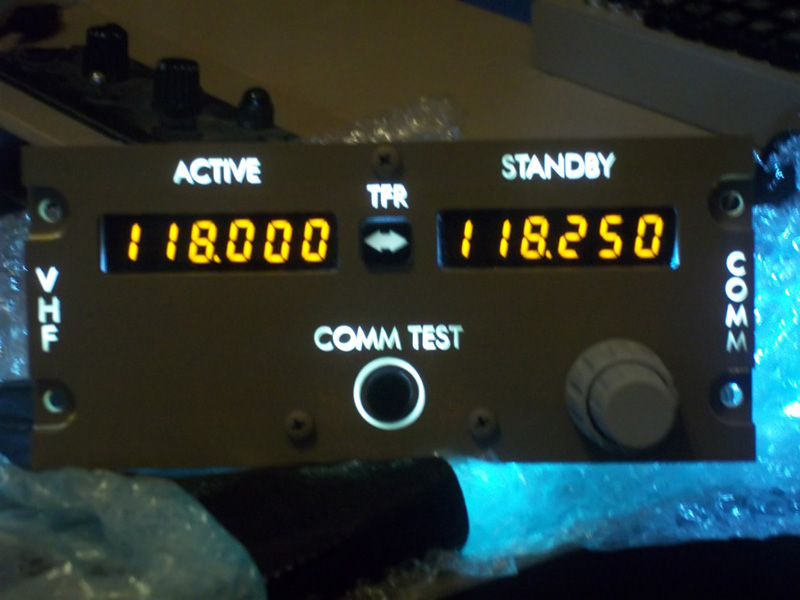
As soon as the radio is plugged into a USB slot, the
backlighting on the 767 COMM module will instantaneously
come to life. There are about 8 LEDs that constitute the
backlighting system; these LEDs are extraordinarily
bright and easily penetrate the face-panel of the 767 COMM
module.
In fact, this is not strictly true. Alejandro from Opencockpits
has suggested the power supply on the back of the COMM module be
used as a dimmer. The way that this is achieved is by plugging a
5V power supply into the back of the module, but regulating the
5V feed somehow (perhaps using a variable resistor) so that the
backlighting can be dimmed and brightened. Alternatively, the
"R5" resistor (see circuit diagrams in supplied documentation)
can be removed and replaced with a 1K Ohm variable resistor.
Whilst this is a perfectly viable option, I wouldn't recommend
doing this unless you have sufficient electrical experience and
are comfortable using a soldering iron.
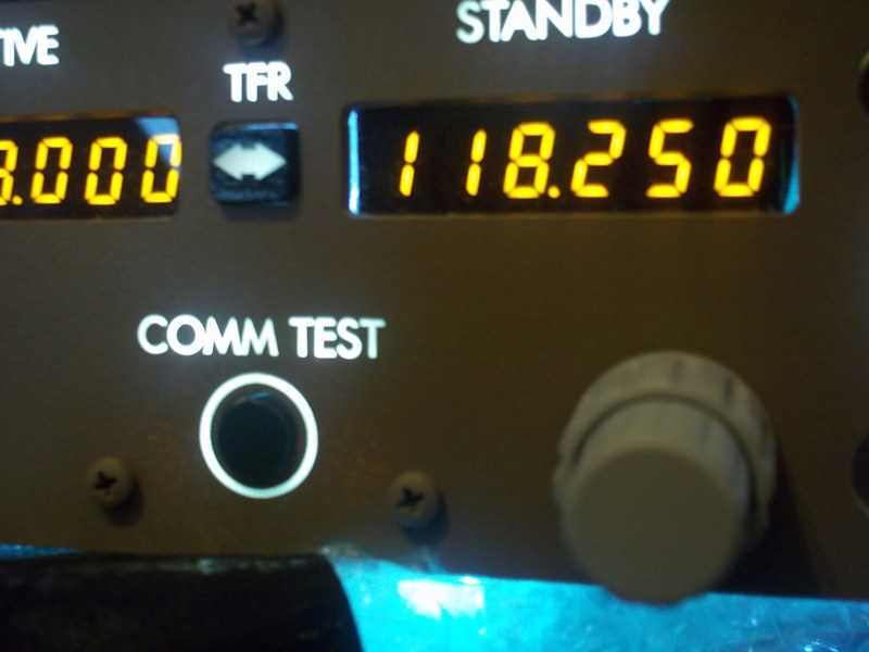
Furthermore, since the panel is professionally CNC cut and
engraved, the white “label” areas (for example,
the word “COMM” on the radio) appear to glow more prolifically
than the brown parts of the radio. If anyone
has ever been into a 757/767 cockpit at night, this “glow”
effect from backlit panels will be very familiar.
It is very important to note that this backlighting cannot be
controlled. As soon as the module is plugged in via
USB, it will illuminate and there is no way to turn it off (not
that you'd want to!) unless the module is
unplugged. Strangely, the module remains illuminated even
after
my PC has shut down. In other words, the
only way to completely turn off the module is to unplug it.
One the drivers had installed, I decided to test the software
using the testing program built into the latest
version of SIOC; version 4 or higher of SIOC is required to use
this feature. SIOC is completely free to
download and use, and it is available on Opencockpits' website
as a download.
To start the testing regime, double click the SIOC executable
file (once installed, of course). This will bring up
the SIOC main window:
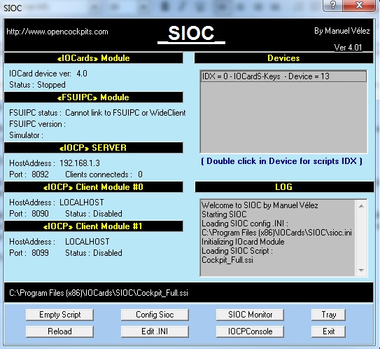 |
Once established on the main window, click on the “SIOC Monitor” button. This will bring up a small window, upon which the “IOCARD COMM” entry should be seen. Double clicking this entry will bring up the module testing software.
 |
 |
 |
 |
The testing interface is fairly self explanatory. Clicking the “ALL ON” button will illuminate all of the 7- segment displays and decimal points, and, obviously, “ALL OFF” will reverse this command. The multitude of squares in the top half on the interface tells the user which switches are currently turned “ON”. This is a handy way of checking if all the switches on your module are functioning to your satisfaction. Furthermore, rotating either one of the rotary encoders will cause various inputs to flicker, since a 24-step rotary encoder works by alternating inputs on-and-off through 24 different combinations of inputs. These combinations are represented on screen by “flickering inputs”.
Once one has tested the module as much as they wish, the testing interface should be closed. The next step is to configure the module to work with FS2004/FSX (X-Plane is also supported as far as I know, but I do not own it, so I cannot vouch for this).
Configuring the module for FS2004/FSX – The IOCModules Program
Interfacing to FS2004/FSX is achieved through one of two means.
Firstly, the Opencockpits SIOC software can be used. Use of SIOC requires knowledge of programming, although this method is the most powerful (as in the module is most configurable when using SIOC). This is covered in a later section.
Alternatively, Opencockpits have created an application called “IOCModules”. This program is designed for people that either do not have the experience to program, or simply to not want to spend time doing so. The IOCModules program is a simple executable file that runs alongside FS2004/FSX that allows Flight Simulator to interface to the module.
To download the IOCModules application, simply go to the product page of the 767 COMM module and go to the “downloads” tab. The application can easily be downloaded free of charge and installed.
Using the IOCModules program is painfully simple; once you have started a flight in FS2004/FSX, double click the “IOCModules” executable file. This will instantly allow the radio to interface to Flight Simulator and it will work perfectly with most aircraft that carry a COMM radio.
That's all there is to it!
Operation of the Radio
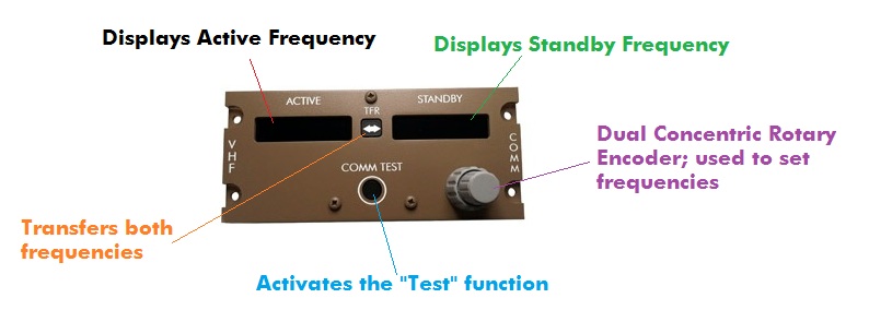 |
The above annotated diagram details the functions of the 767 COMM module. As can be observed, the exact functions of the real-world radio are maintained in Opencockpits' product.
Both frequency displays have a single decimal point located between the third and fourth digits; for example, “123.25”.
The rotary encoder that selects the frequencies is dual-concentric. This means that the encoder is, in effect, two rotary encoders turned into one; the “fatter” bottom encoder rotates around the outside of the “thinner”, taller encoder. The larger encoder controls the frequency integers, whilst the smaller encoder controls the numbers after the decimal place. The encoder has a very satisfying “click” feel to it; identical to the real-world counterpart. Furthermore, the rotary encoders are very precise and do not “lag” when turned properly; less can be said for similar products on the market (not to name names of course!).
The “TFR” and “TEST” buttons function as normal push switches. These switches are tactile, which means that they “click” when pressed. The “TEST” button causes all displays to become filled with the number “8” and all decimal points to illuminate.
Overall, the operation of the radio is excellent. Everything functions as it should, the frequency change updates (the time between FS and the Opencockpits radio to synchronize) are fluid, and the backlighting acts as the hardware equivalent of the “cherry on the cake”.
Please note however, that whilst the radio works perfectly fine when interfaced to FS2004/FSX using the IOCModules program, “cold and dark” functionality is not supported. Simply put, this is whereby, after turning the aircraft's electrical supply off, the radios should also turn off. This can, however, be achieved by using SIOC.
Configuring the Module for FS2004/FSX – SIOC
<NOTE: SIOC is software that can be freely downloaded from Opencockpits' website. It can be used to interface the radio in a more “powerful” way; cold and dark support, amongst other features, can easily be implemented. Furthermore, SIOC unlocks the ability for one to use the radio in different ways; for example, if desired, the “COMM TEST” button could be used to control the autopilot.>
[This section is intended to be a brief “overview” of what can be achieved through SIOC and the 767 COMM module. If you seek specific information on how to make a script, or just need help getting started, feel free to contact me through Mutley's Hangar.]
Although this section of the review will not cover step-by-step how to control the module in SIOC (such material would be out of a reviewer's remit), it will contain several SIOC examples that have been used by people within the FS community to interface their 767 COMM module.
The best example of a SIOC script for the 767 COMM module is a script made by Nico Kaan, a Boeing 767 cockpit builder and developer of the fabled “Lekseecon” software for the Level-D 767. Nico has designed a script that allows the user to interface the 767 COMM module to the Level-D 767 in FS2004 or FSX. For this script to work, the “Lekseecon” software must also be installed; once again however, this software is free of charge, and takes literally seconds to install.
The script below shows what can be achieved through SIOC; a brief description of the coding can be found underneath, although it is assumed that one already knows the basic workings of the SIOC software. For more information, Nico Kaan's site contains (literally) hundreds of SIOC tutorials and examples; be sure to visit his website ( http://www.lekseecon.nl/sioc.html
|
////////////////////////////////////////////////////////////////////// Var 852 Static { IF &COM1Lft = 1 { &LDispl = v852 } ELSE { &RDispl = v852 } } Var 9001 name LDispl { L0 = &LDispl L1 = MOD L0 16 IF L1 = 10 { &D_COM1LZ = -999999 // blank &D_COM1L0 = -999999 // blank &D_COM1L1 = -999999 // blank &D_COM1L2 = -999999 // blank &D_COM1L3 = -999999 // blank &D_COM1L4 = -999999 // blank } ELSE { &D_COM1L0 = MOD L0 16 L0 = DIV L0 16 &D_COM1L1 = MOD L0 16 L0 = DIV L0 16 &D_COM1L2 = MOD L0 16 L0 = DIV L0 16 &D_COM1L3 = MOD L0 16 L0 = DIV L0 16 L1 = MOD L0 16 &D_COM1L4 = L1 IF L1 = 8 { &D_COM1LZ = 8 } ELSE { &D_COM1LZ = 0 } } } Var 853 Static { IF &COM1Lft = 1 { &RDispl = v853 } ELSE { &LDispl = v853 } } Var 9002 name RDispl { L0 = &RDispl L1 = MOD L0 16 IF L1 = 10 { &D_COM1RZ = -999999 // blank &D_COM1R0 = -999999 // blank &D_COM1R1 = -999999 // blank &D_COM1R2 = -999999 // blank &D_COM1R3 = -999999 // blank &D_COM1R4 = -999999 // blank } ELSE { &D_COM1RZ = 0 &D_COM1R0 = MOD L0 16 L0 = DIV L0 16 &D_COM1R1 = MOD L0 16 L0 = DIV L0 16 &D_COM1R2 = MOD L0 16 L0 = DIV L0 16 &D_COM1R3 = MOD L0 16 L0 = DIV L0 16 L1 = MOD L0 16 &D_COM1R4 = L1 IF L1 = 8 { &D_COM1RZ = 8 } ELSE { &D_COM1RZ = 0 } } } Var 779 Static { &COM1Lft = TESTBIT v779 0 &O_DPCOM1L = TESTBIT v779 2 &O_DPCOM1R = TESTBIT v779 2 } Var 9003 name COM1Lft // active? { IF &COM1Lft = 1 { &LDispl = v852 &RDispl = v853 } ELSE { &LDispl = v853 &RDispl = v852 } } Var 9004 name tfr Link IOCARD_SW Device 5 Input 6 Type P { v510 = &tfr v511 = CHANGEBITN 0 v510 } Var 510 Static Value 1 Var 511 Static Value 0 Var 517 Static Var 518 Static Var 602 Static Link IOCARD_SW Device 5 Input 2 Type P // test lights via Test button Var 9005 name RO_RCOM1H Link IOCARD_ENCODER Device 5 Input 0 Aceleration 1 Type 2 { L0 = &RO_RCOM1H * -1 v517 = ROTATE 0 127 L0 } Var 9006 name RO_RCOM1L Link IOCARD_ENCODER Device 5 Input 4 Aceleration 1 Type 2 { L0 = &RO_RCOM1L // * -1 v518 = ROTATE 0 127 L0 } Var 778 Static name COMM1Act { // this var is set by LEKSEECON and represents the active frequency // just pass it to the generic FSUIPC offset in bcd format, without leading '1' L0 = &COMM1ACT - 10000 &FO_COMM1Act = TOBCD L0 } Var 9007 name FO_COMM1Act Link FSUIPC_OUT Offset $034E Length 2 // ACTIVE display in COM737 Var 9008 name D_COM1LZ Link IOCARD_DISPLAY Device 5 Digit 0 Numbers 1 Var 9009 name D_COM1L0 Link IOCARD_DISPLAY Device 5 Digit 1 Numbers 1 Var 9010 name D_COM1L1 Link IOCARD_DISPLAY Device 5 Digit 2 Numbers 1 Var 9011 name D_COM1L2 Link IOCARD_DISPLAY Device 5 Digit 3 Numbers 1 Var 9012 name D_COM1L3 Link IOCARD_DISPLAY Device 5 Digit 4 Numbers 1 Var 9013 name D_COM1L4 Link IOCARD_DISPLAY Device 5 Digit 5 Numbers 1 // STANDBY display in COM737 Var 9014 name D_COM1RZ Link IOCARD_DISPLAY Device 5 Digit 6 Numbers 1 Var 9015 name D_COM1R0 Link IOCARD_DISPLAY Device 5 Digit 7 Numbers 1 Var 9016 name D_COM1R1 Link IOCARD_DISPLAY Device 5 Digit 8 Numbers 1 Var 9017 name D_COM1R2 Link IOCARD_DISPLAY Device 5 Digit 9 Numbers 1 Var 9018 name D_COM1R3 Link IOCARD_DISPLAY Device 5 Digit 10 Numbers 1 Var 9019 name D_COM1R4 Link IOCARD_DISPLAY Device 5 Digit 11 Numbers 1 Var 9020 name O_DPCOM1L Link IOCARD_OUT Device 5 Output 20 Var 9021 name O_DPCOM1R Link IOCARD_OUT Device 5 Output 21 /////////////////////////////////////////////////////////////////////////////// |
Now; I can guarantee that you will almost certainly be thrown by the script above if you have never used SIOC before. In fact, I myself do not understand what every single line of code achieves; I leave that up to Nico and his super-human SIOC skills.
The sections that define the variables “IOCARD_ENCODER” interface the COMM module's rotary encoders to FS2004/FSX. The “acceleration” value is used to determine the “speed” of the rotary encoder (ie how fast the frequency values change in respect to how quickly you're turning the rotary encoder).
The “acceleration” function is an example of an advantage of using SIOC with the 767 COMM module; although much more simple, one simply cannot achieve this level of customization with the IOCModules program.
The “IOCARD_SW” is a reference to the “COMM TEST” and “TFR” buttons. As previously mentioned, SIOC has the ability to assign these switches to whatever one wishes. Nico has, however, in this script, maintained the normal functionality of the buttons (ie they work how they normally would do on a real 767 radio).
All of the “IOCARD_DISPLAY” variables define the 767 module's 7-segment displays. It is, through SIOC, that Nico has been able to implement the cold and dark functionality of the 7-segment displays. On the Level-D 767 software, if I cut electrical power to the radios, the 7-segment displays will turn off (the backlighting, however, remains turned on; as previously mentioned this is because the backlighting is controlled by a separate circuit that cannot be accessed through software).
OCM Configurator
[NOTE: This program ONLY works for the Level-D 767 and the upcoming Level-D 757.]
Nico Kaan has kindly provided a small tool, named “OCM Configurator”, which, when started, instantaneously configures the SIOC software to work with your 767 COMM module; no knowledge of scripting is required.
This tool can be downloaded free of charge when the Lekseecon program is downloaded (they're included in the same installation). The advantage of the OCM Configurator program is that one can achieve functions such as cold and dark functionality without having to do any advanced coding themselves.
Documentation and Support
A 5-page PDF manual is provided with the 767 COMM module (available to download on the product's page on Opencockpits' website).
Despite it being only 5 pages in length, the manual contains a surprising amount of detail, along with a few helpful annotated diagrams.
As with most Opencockpits' products, the manual isn’t translated very well, but it gets the “gist” across and, for a product that's so simple to operate, it doesn't detract from the enjoyment of the module.
Support is available through Opencockpits website. Generally, the support staff are more than happy to help and usually reply within 2 days of the initial question (not counting weekends).
![]()
Verdict
Simply put, this module is truly excellent.
The lack of Boeing 767 products available on the market is a
problem that is finally being addressed by Opencockpits. The
COMM module itself functions perfectly for any cockpit
setup; indeed, as this review has proven, the module is
compatible with many aircraft.
Built-in backlighting and a very competitive price makes
this module something to consider when choosing what your
next hardware purchase will be.
Pros:
● Backlighting is fantastic
● Precisely cut CNC panel looks great
● Works perfectly with FS2004/FSX (and, supposedly, X-Plane)
● Easy USB connection; no need to install drivers
● Ability to implement cold and dark support through SIOC
● Brightness of 7-segment displays can be controlled through
software
● Price!
Cons:
● Perhaps the manual, but the product itself is faultless
Mutley's Hangar score of
10/10
![]()
Jack
Whaley-Baldwin
Review machine Spec: Core i7 920 OC @ 3.8 Ghz |
6Gb Tri-Channel DDR3 Ram |GTX285 Graphics |Windows 7
64bit Home Premium