Introduction
Servo motors are electronic motors that adjust their positioning
according to feedback obtained from a source. For example, a
central-heating thermostat is an example of a servo (but not a
servo motor), as it constantly adjusts itself according to
feedback given from the surrounding air temperature.
Servo motors can be widely obtained in many different qualities,
shapes and sizes. Micro-servos to advanced industrial servo
applications are common all over the world, and due to their
flexibility and ability to achieve high levels of accuracy, they
can be used in just about anything, including Home Cockpit
fittings, which it what this review focuses on.
Opencockpits, a Spanish company that develops hardware and
software for the three main flight simulators, FS2004, FSX and
X-Plane, have successfully designed an electronic card that
controls servo motors, as an addition to their IOCard (Input/Output
Card) range of products.
Many Cockpit Builders use this electronic card to drive various
apparatus in their dedicated Aircraft-Cockpit Simulators, and
repeatedly talk about their positive experiences with the
device.
But does it live up to the hype?
The USBServos Card
Opencockpits have engineered the adequately named “USBServos
Card”, which, unsurprisingly, controls servo motors. This card
can be purchased from Opencockpits, or alternatively, Aviation
Megastore, the only official source of Opencockpits hardware.
It is reasonably priced at 25 Euros, + VAT, excluding shipping.
The item is despatched quite quickly from what I experienced.
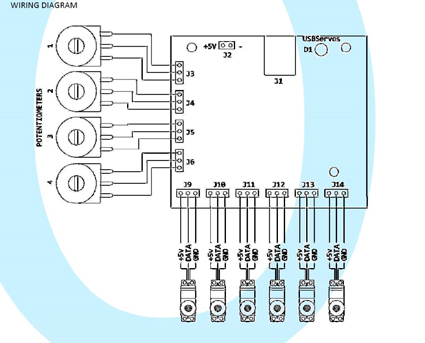
This card gives six three-pin outputs designed to be connected
to any conventional servo motor. Supported brand types are
Futaba, Hitec, JR, Airtronics, and many more as I have managed
to connect Etronix servos to the card too.
There is a small Red LED on the USBServos Card which only
illuminates when it is being supplied with a 5V Power Supply and
is receiving software input from your computer. This is very
handy as you will be able to see if the card should be working
or not – A lifesaver when testing servos with the card.
Testing
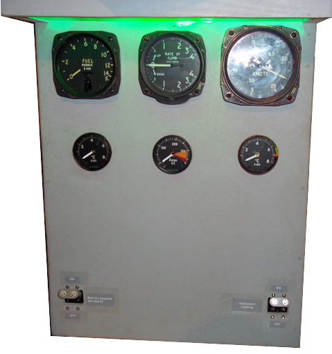
After purchasing the Card, I managed to build two servo driven
applications for my home simulator. They were, simply put,
real-world aircraft instruments that had their insides stripped,
and replaced with a servo with the needle attached.
So, I had instruments driven by servos, but no way to test them.
This is where Opencockpits provide further assistance.
Navigating to the downloads section of the Opencockpits website,
one can download a program which, once installed, presents the
user with a very friendly and easy to use testing interface.
This interface is all covered within the manual. Basically, you
can individually adjust the values of the six servo outputs
using the slider along the bottom. This slider increases or
decreases the value with the precise movements of the keyboard
left and right arrow keys.
I found this testing program to be very useful and helpful. I
successfully managed to move my Airspeed and Vertical-Speed
Indicators to their full extents, and I managed to note down
what values I needed to input into the SIOC Script (explained
later).
The four fluctuating values that you can see on the left-hand
side are those of the analogical potentiometer inputs. This
works to somewhat the opposite way of the servo testing. If you
adjust the potentiometer values in real-life, the values will
change on screen, just as they should with Pot inputs.
The videos you can see below are me using the USBServos Software
to test my ASI and VSI gauges, respectively.
Reliability
I have powered-up the USBServos Card countless times and it never
fails to work.
It's good to see that when I plug the card into the USB slot,
the Servo needle always returns to the same place instead of
rotating to an incorrect value.
Furthermore, whenever I adjust the values in the USBServos
software, the needle always moves at the same pace, hitting the
appropriate airspeeds at the values I calculated beforehand.
Perfect.
The USBServos Card is a wonderful example of reliability! It
never fails to impress me with how it manages to accurately plot
the course of my instrument gauges and bring them safely back
home to the fabled zero point.
In addition, I tested each output with a multimeter and every
time the same voltage pulses (this is how the servo data is
given out) were the same.
Very reliable!
Power supply
The card requires you to connect your own 5V power supply to the
card. However, the connection is a small and very fragile
two-pin connector, and you must make/obtain your own connecting
device.
I was a little disappointed with this, as I reckon that
Opencockpits could've supplied a small lead to connect to the
card, especially because the pins are likely to break if the
wrong connector is punched through them.
Luckily, it wasn't hard for me to source the correct connector
and after a quick visit to the local electronics store I was
up-and-running with the USBServos Card.
| Connections to the Servo pins Unfortunately, Servo manufacturers don't tend to standardize in terms of how they arrange their servo leads. Each servo, as previously mentioned, as three wires, namely 5V (Power), GND (Ground), and DATA (Voltage pulses). Servo brands like to swap these around, so whilst on one servo it may be arranged 5V, GND, DATA, on another servo it will most likely be arranged differently. This has given Opencockpits little choice in how they go about arranging the connectors on their USBServos Cards. Eventually, they settled for 5V, DATA, GND, which of course is not the norm for any servo, due to the manufacturer's ignorance (see above). Due to the fact that Opencockpits have arranged their card like this, and that manufacturers don't standardize, it is up to the user to swap the wires around on the servo to comfortably fit the USBServos Card. In my case, I produced small conversion leads/plugs which allow me to simply slot my servo in one end, and have it swapped around in order to connect to the Opencockpits card at the other. I would be happy to circulate these conversion leads around the FS community for a small fee for those who require it. This is another case where maybe Opencockpits could've covered a little better, possibly by selling such leads as part of their shop or giving a detailed guide on how to convert them. |
 |
What Opencockpits do provide, however, is a table in their
manual instructing on how different brands of servo swap around
to become compatible with the Opencockpits Card. It did find
this useful, so I suppose it makes up for the lack of physical
conversion kits between Card and Servo.
[NOTE: THE FOLLOWING SECTION IS QUITE DETAILED AND COMPLEX. IT
MAY BE DIFFICULT FOR SOME USERS TO UNDERSTAND THE SIOC LANGUAGE,
OR SIOC ALTOGETHER]
Configuring the USBServos Card –
SIOC and FS
Whilst testing the servo does provide a small extent of
enjoyment, it is actually seeing your servo-driven Modules that
give the real sense of achievement.
For the USBServos Card to communicate with FS2004/FSX, and
vice-versa, the user will need to configure their card in the
SIOC Software. This involves two complex steps: Setting up the
SIOC.ini file, and designing a working SIOC Script.
SIOC.ini is a small but very essential file provided with every
correct installation of the free ware SIOC Software. It is the
initialization file that SIOC reads every time it starts up.
Think of it as “the brain” behind SIOC – Whatever the SIOC.ini
file says, SIOC carries that task out.
The manual doesn't teach detailed instructions on how to set
this up with the USBServos Card, so a little legwork is
required. Basically, one must add the line [USBSERVOS=N,X],
where N is the “index” number of the USBServos Card (ie how many
you have in your system. Card number one = 0, Card number two =
1, and so on).
Next, below that line, the user must add the following
instruction [deviceUSB=M], where M is the device number of the
USBServos Card. To find the device number, one can look in the
main SIOC window, found after starting SIOC.exe.
For further clarification, please look at my SIOC.ini file
below, setup up perfectly for the use of the USBServos Card.
//
[SIOC]
IOCP_port=8092
IOCP_timeout=4000
Minimized=Yes
toggle_delay=20
CONFIG_FILE=ServoVSI.ssi
[IOCARDS MODULE]
IOCard_disable=No
IOCard_LPT=No
[DEVICE INFORMATION]
USBSERVOS=0,77
deviceUSB=2132
[FSUIPC MODULE]
FSUipcdisable=No
FSUipcRefresh=50
[IOCP CLIENTS MODULES]
IOCPini_delay=3000
IOCPclient0_disable=Yes
IOCPclient0_host=localhost
IOCPclient0_port=8090
IOCPclient1_disable=Yes
IOCPclient1_host=localhost
IOCPclient1_port=8099
[SOUND MODULE]
Sound_disable=Yes
Volume=100
//
Please note that the values of 0,77 and 2132
must be substituted depending on your PC.
Also note the line [CONFIG_FILE=ServoVSI.ssi]. This is where we
tell SIOC.ini what our SIOC script is, and where it is located
(the SIOC file should be always located in the main SIOC Folder
directory).
To design a SIOC Script, many hours of studying are required. It
is far too complex an affair to explain in this review, so at
this point I'd like to point you towards
Nico Kaan's fantastic
site
![]() , which gives hundreds of SIOC examples and exercises for
everyday use.
, which gives hundreds of SIOC examples and exercises for
everyday use.
For those that are interested, below is my current SIOC script,
designed to drive a VSI and ASI gauge to FSX. I have named it
“ServoVSI.ssi” hence why it is called so in the SIOC.ini (see
above).
//
Var 8500, Link
FSUIPC_IN, Offset $02C8, Length 4, Type 1
// Vertical Speed
{
L0 = V8500 * 0.7895
// FSUIPC conversion, L0=VS
L0 = ABS L0
// L0 not signed
L2 = L0
IF L0 <= 1000
// First sector
{
L1 = L2
* 0.085
// (85 steps/1000 values) = 0.085
}
ELSE
// Is a greater value
{
L2 = L0
- 1000
// L2 only
have values for next sector
IF L0
<= 2000
// Second sector
{
L1 = L2 * 0.052
// (52 steps / 1000 values) = 0.052
L1 = L1 + 85
// Add steps of others sectors
}
ELSE
{
L2 = L0 - 2000
// L2 only have values for next sector
IF L0 <= 4000
// 3. Sector
{
L1 = L2 * 0.028
// ( 56 / 2000) = 0.028
L1 = L1 + 137
// Add steps of others sectors 52 + 85
}
ELSE
{
L2 = L0 - 4000
// L2 only next sector (Value-1000-1000-200
IF L0 <= 6000
// 4. Sector
{
L1 = L2 * 0.035
// ( 70 / 2000) =0.035
L1 = L1 + 193
// Add steps of others sectors 56+52+85
}
ELSE
// Out of range
{
L1 = 263
// Max. position
}
}
}
}
IF V8500 < 0
// If vs is negative
{
&VSI =
607 - L1
// Subtract from center
}
ELSE
{
&VSI =
607 + L1
// Else add to center
}
}
Var 0500, name
VSI, Link USB_SERVOS, Output 4, PosL 345, PosC 607, PosR 870,
Type 2
// vsiservo
Var 9003, name
IAS, Link FSUIPC_IN, Offset $02BC, Length 4
// IAS from Sim
{
L0 = DIV &IAS 128
L1 = L0 * 1.91 //
Calculate Servo Slope
L2 = L1 + 271.5 //
Calculate Servo Intercept
V9000 = L2
}
Var 9000, name
Servo3, Link USB_SERVOS, Output 3, PosL 271, PosC 606, PosR 940,
Type 2
// ASI gauge
//
As you can see, the SIOC script requires a
huge amount of calculating and work. Thankfully, for those note
wishing to input so much effort a very quick SIOC tutorial for
the USBServos Card is provided in the manual, and it seems to
work okay. It is a tutorial on how to get a small VSI gauge
working with SIOC (although not nearly as complex and detailed
as above).
To calculate the scales of my gauges used with the USBServos
Card (ie to tell the real-life gauge how much to move for every
unit the FSX gauge moves), I visited yet another useful website,
this time The Baron 58 Cockpit Simulator website
![]()
Documentation
The documentation, referenced a few times throughout this
review, draws very mixed opinions from me.
To describe what I didn't like, I was unhappy at the inclusion
of a proper SIOC.ini setup example. Secondly, I think a guide or
something similar detailing how to design the 5V Power Supply is
needed somewhere within the USBServos Card manual.
Also, as I mentioned above, the information included on how to
get it working with SIOC, and also how to get the SIOC.ini file
set up, is patchy at best.
 |
 |
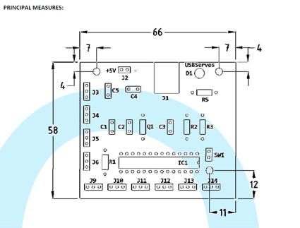
However! It should never be said that the documentation is completely useless. It does, towards the beginning, include some very clear and informative circuit diagrams, dimensions, and even a colour guide on how to convert your Servo leads for USBServos Card compatibility.
I think with a little work the documentation could become much easier, especially because manuals are so valuable to beginners with such electronic cards. As it stands, the manual is a little unfriendly for beginners, except for the diagrams at the beginning which are excellent.
![]() Verdict
Verdict
The USBServos Card is definitely an excellent
purchase for every cockpit builder out there. Its
unparalleled reliability and ease of use makes it a very
suitable choice for all sorts of cockpit applications.
I would've liked a little more effort on the documentation
front, and potentially some more advice on how to convert
the servo leads and also how to connect to the 5V power
supply up, but nonetheless I am universally impressed with
this product.
I hope Opencockpits continue their long-established fashion
of producing high-quality and easy-to-use cockpit parts!
Pros:
Very Reliable Card
Reasonable Price
Works with many different simulator programs
Testing software is great and works very well
Four analogue potentiometer connectors included on the card
Cons:
Documentation rather patchy
Fragile and tricky to connect to 5V power input
My Score: 9/10
![]()
Jack
Whaley-Baldwin
Review machine Spec: Core i7 920 OC @ 3.8 Ghz |
6Gb Tri-Channel DDR3 Ram |GTX285 Graphics |Windows 7
64bit Home Premium
|
|